Gridbots Magneto-TUBESCAN boiler tube inspection robot


HOME » INDUSTRIAL » ROBOTICS SERVICES » MAGNETO-TUBESCAN

Gridbots Magneto-TUBESCAN

Boiler Tube Thickness Mapping Robot

Magneto-TUBESCAN is a magnetic climbing robot built to measure the wall thickness of power plant boiler waterwall tubes – up to 10 tubes in a single run – using an array of immersion ultrasonic probes.

As it climbs the waterwall, every probe records tube thickness continuously at 0.1 mm linear resolution with ±0.1 mm measurement accuracy. The data is stitched in real time into a 3D thickness map of the boiler that clearly marks healthy tubes, sections to monitor, and critical thinning that needs replacement.

Permanent-magnet adhesion, twin PMSM drives, an encoder and a 6-DOF IMU let the robot climb vertical and inclined waterwalls while knowing exactly where every reading was taken – so each thin spot can be found again for repair.

TUBESCAN replaces scaffolding and slow manual spot-gauging, cutting boiler outage time and giving plant engineers complete, traceable tube condition data for every shutdown.
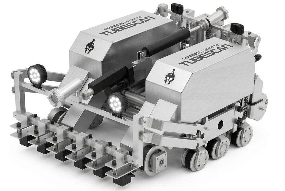
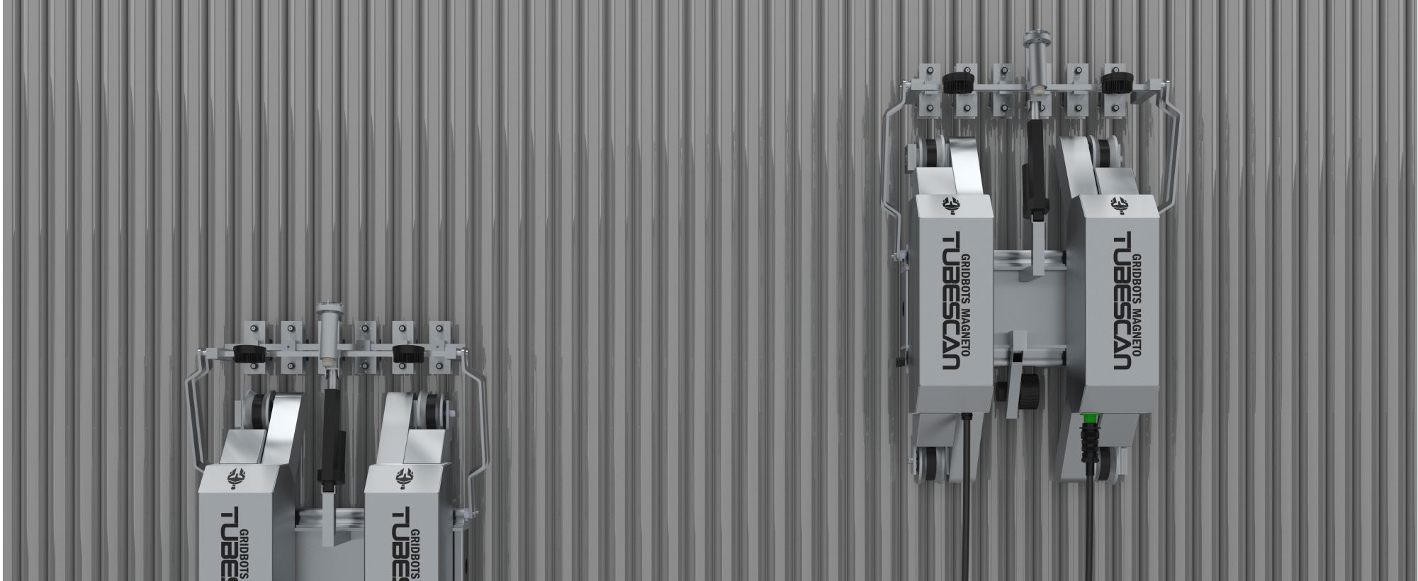
Magneto-TUBESCAN scanning boiler waterwall tubes

10
Tubes per run
0.1 MM
Linear resolution
±0.1 MM
Thickness accuracy
3D
Boiler thickness map


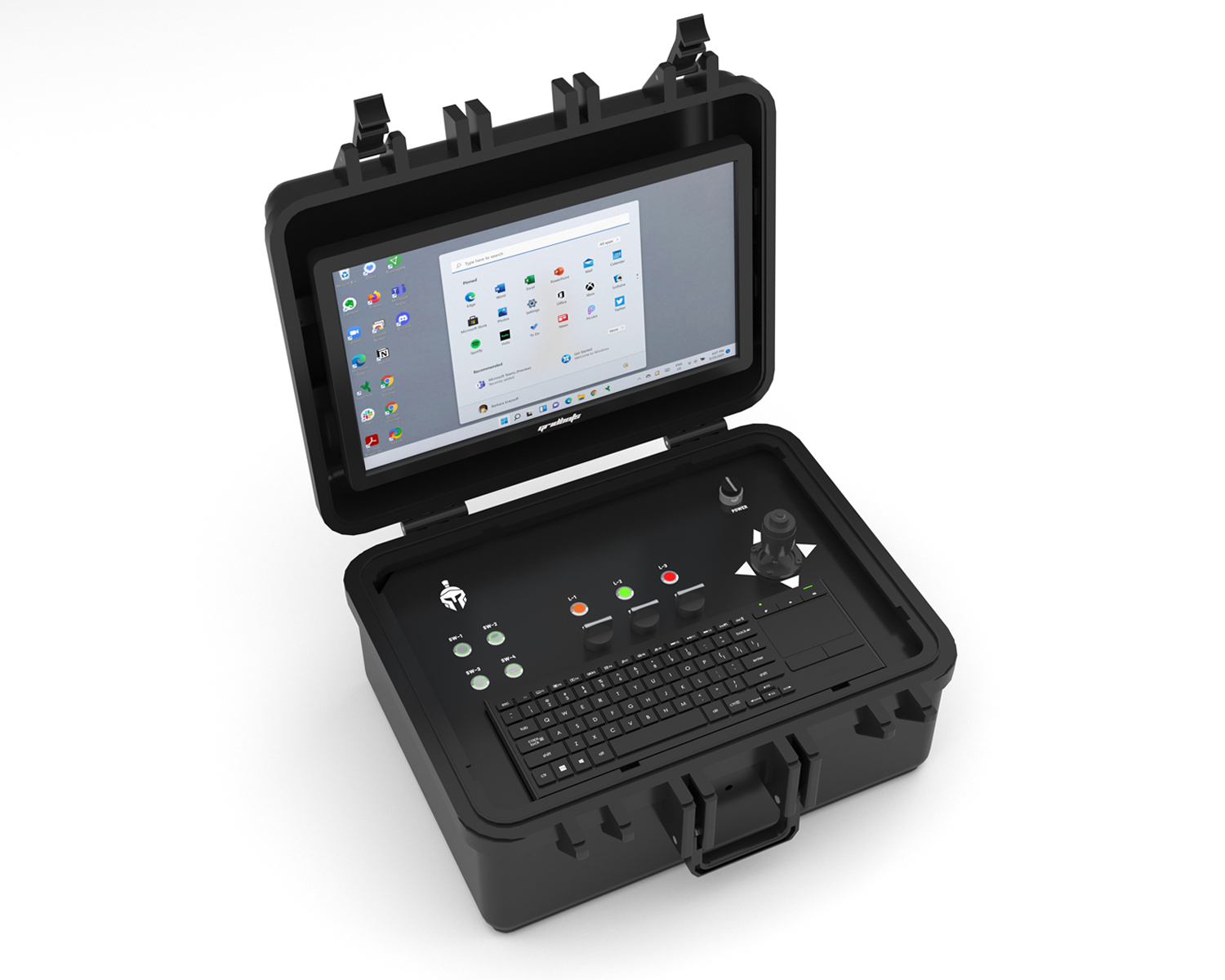
TUBESCAN operator control unit with live thickness map

OPERATOR CONTROL UNIT

The 12” touch-screen operator control unit drives the robot and runs the TUBESCAN mapping software. It shows live camera video, the A-scan of each probe, a running thickness trace for all 10 tubes and the robot’s position on the waterwall.

As the robot climbs, readings are colour-coded against your nominal and minimum allowable thickness, so critical spots appear on screen the moment they are scanned. At the end of each run the data joins the boiler’s 3D map, and a report with tube-by-tube results is generated automatically.


Ultrasonic Thickness Measurement

Ultrasonic testing sends a short, high-frequency sound pulse into the tube wall. The pulse reflects from the inner (water-side) surface and returns to the probe. Because sound travels through steel at a known, constant velocity, the time it takes for the echo to return gives the exact remaining wall thickness – measured from outside the tube, with no cutting and no access to the inside.

Thickness = (Velocity in steel × Echo time) ÷ 2

Typical longitudinal velocity in carbon steel ≈ 5,920 m/s. A 6.0 mm wall returns its echo in about 2 microseconds.


Immersion Probe Array on Waterwall

Cross-section: one water-filled probe shoe on each tube crown

Robot probe beam (10 channels) Water column Thinned tube detected Waterwall tubes Membrane

Each probe sits in a water-filled shoe that follows the tube crown, giving perfect acoustic coupling without gel and without touching the tube.

A-Scan: Reading the Echo

Signal from one probe as seen on the controller

Measurement gate Initial pulse Water / tube surface 1st back-wall 2nd 3rd Echo-to-echo time → thickness

Echo-to-echo measurement between successive back-wall echoes cancels the water path and any oxide layer, giving true metal thickness.

Immersion Coupling

Water-filled shoes couple sound into the tube with no gel and no wear, so readings stay stable across rough, scaled tube surfaces.

10 Channels at Once

One probe per tube crown measures ten tubes simultaneously in every climb – ten times the coverage of single-probe gauging.

Position-Tagged Data

Encoder and IMU tag every reading with tube number and elevation to 0.1 mm, so any thin spot can be located for repair.


3D Thickness Mapping

Every run is merged into a 3D model of the boiler waterwall. Each tube is colour-coded along its full height, so engineers can see at a glance which sections are healthy, which need to be watched, and which are critical – and plan tube replacement before a failure forces an unplanned outage.


3D Tube Condition Map

10 tubes × 6 m elevation, nominal wall 6.0 mm

OK ≥ 5.4 mm Monitor 4.8–5.4 mm Critical < 4.8 mm

2D Thickness Map (Unrolled)

Same scan – continuous colour scale, tube number vs. elevation

4.0 mm
6.2 mm

Thickness Profile Along Tube

Tubes 3, 6 and 9 – continuous 0.1 mm-step readings (sampled for display)

Minimum Thickness per Tube

Lowest reading found on each tube in this run

Condition Distribution

Share of scanned tube length in each condition class

Accuracy vs. Reference

TUBESCAN readings vs. calibrated reference on test tubes

CONDITION CLASSIFICATION

ClassRemaining WallExample (6.0 mm nominal)Recommended Action
OK≥ 90% of nominal≥ 5.4 mmNo action – re-scan at next scheduled outage
MONITOR80 – 90% of nominal4.8 – 5.4 mmTrend at every outage, check for erosion source
CRITICAL< 80% of nominal or below t-min< 4.8 mmPad weld or tube replacement before restart

Thresholds are fully user-configurable to match your boiler design code, tube material and plant standards.


SAMPLE RUN REPORT

TubeMin (mm)Avg (mm)Min at ElevationWall LossStatus

Maps, charts and the report show representative data for illustration. Real results come from your boiler scan.


Features


Measures up to 10 boiler tubes in a single run

Immersion ultrasonic probes – no gel, no contact wear

0.1 mm linear resolution, ±0.1 mm accuracy

3D boiler map with OK / Monitor / Critical zones

Real-time inertial tracking (6 DOF)

Climbs straight and inclined waterwalls

Permanent magnet adhesion, all wheels power driven

3 FHD cameras for visual tube inspection

Outage-to-outage trend comparison

Up to 250 m umbilical – operate from outside the furnace


Magneto-TUBESCAN on boiler waterwall

Applications


Coal-Fired BoilersWaterwall erosion from soot blowers, burners & fly ash
CFBC BoilersRefractory-interface and bed-zone tube wastage
Biomass & WtE BoilersCorrosion from chlorides and aggressive fuels
Recovery BoilersPulp & paper recovery boiler wall tubes
HRSG & Utility BoilersMembrane wall panels and water-cooled surfaces
Life AssessmentRLA studies & outage planning with trend data

INSPECTION WORKFLOW

01
PrepareLight surface cleaning; set nominal & t-min
02
ScanClimb 10 tubes per run with live readings
03
MapRuns merge into the 3D boiler model
04
ActReport critical tubes with exact location

TUBESCAN vs. MANUAL UT GAUGING

ParameterManual UT with ScaffoldingMagneto-TUBESCAN
AccessFull furnace scaffoldingMagnetic climbing – no scaffolding
Tubes per pass110
Data densitySpot readings, typically every 0.5 – 1 mContinuous, every 0.1 mm
CouplingGel, operator dependentImmersion water column, consistent
Location accuracyHand-marked, approximateEncoder + IMU tagged
OutputPaper sheets / spreadsheet3D map, trend overlay & auto report
Risk of missing thin spotsHigh between spot readingsVery low – full-length coverage


Specifications

ROBOT

Model SeriesGB-MAGNETO-TUBESCAN
Power DriveTwin 400 Watts PMS Motors
AdhesionPermanent Magnets
Robot Adhesion ForceUp to 500 N
Robot Line SpeedUp to 20 mm/second
Position TrackingWheel Encoder + 6 DOF IMU
Linear Resolution0.1 mm
Cameras3 FHD with LED Illumination
Robot Power Consumption100 W (Average)
Supply TypeSingle Phase A.C. / Battery Pack
Robot Self Weight20 kgs
Supply and Sensor InterfacingVia Umbilical Cable
Cable LengthUp to 250 Meters
Operator Control Unit12” Touch Screen Tablet PC

ULTRASONIC SYSTEM

TechniqueImmersion Pulse-Echo, Echo-to-Echo Mode
Channels10 (one per tube) in a Single Probe Beam
Tubes per RunUp to 10
Probe Frequency5 – 10 MHz
CouplingWater Column in Self-Aligning Probe Shoes
Thickness Range2 – 15 mm (steel)
Measurement Accuracy±0.1 mm
Display Resolution0.01 mm
Tube Outer Diameter38 – 76 mm (probe shoes per tube size)
Tube PitchAdjustable Probe Spacing to Match Waterwall Pitch
CalibrationOn-site Step Block, Velocity Auto-Calibration

MAPPING SOFTWARE

Live ViewsCamera, A-Scan per Channel, 10-Tube Thickness Trace
Maps3D Boiler Model, 2D Unrolled Waterwall Map
ClassificationOK / Monitor / Critical – User-Set Thresholds
Boiler LayoutWall, Tube Number & Elevation Referencing
TrendingOverlay of Previous Outages, Wear Rate per Tube
ExportPDF Report, CSV / Excel, 3D Model Snapshot

SAFETY

TOF Sensors6x
Impact Sensor1x
E-Stop2x
Fall ArrestSafety Rope Anchor

ENVIRONMENTAL

IP Rating54
Temperature5°C to 65°C
Humidity95%, Non-Condensing


TUBESCAN on boiler waterwall
On the Waterwall
Immersion ultrasonic probe array
10-Channel Probe Beam
3D boiler thickness map software
3D Thickness Map
TUBESCAN system with control unit
Complete System


Drawings


TUBESCAN side view drawing
TUBESCAN front view drawing
TUBESCAN top view drawing